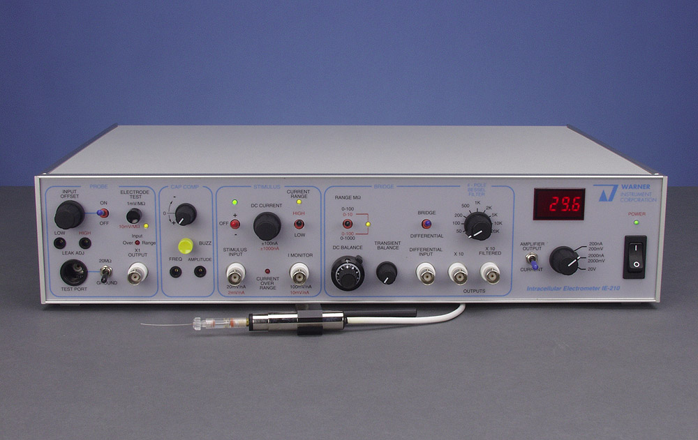
A high impedance electrometer designed specifically for intracellular studies. The instrument consists of two sections; the probe headstage and the controller which contains the signal conditioning, monitoring and power circuitry.
- High impedance microelectrode amplifier for intracellular studies
- Simultaneous current injection stimulation and recording
- Bridge Balance Output gains of x10, x20, and x50
- Capacity Compensation for up to 50 pF
The IE-210 is an intracellular microelectrode amplifier with low noise, low drift and fast response time for recording from high impedance fluid-filled glass electrodes. Current injection (bridge) circuitry permits simultaneous stimulation and recording through a single electrode. These features, in combination with a small lightweight headstage, a 4-pole Bessel low pass filter and optional probe breakaway; make it an ideal instrument for easy, accurate and reliable intracellular recording and current injection.
The Headstage
Fluid-filled microelectrodes can have resistances of over 100 MΩ. To faithfully record potentials with such high resistances, the amplifier input resistance must be at least 100 times greater. The input resistance of the IE-210 is 5000 times greater (5 x 10¹¹Ω) to assure accurate measurements with high resistance electrodes.
To maximize the bandwidth of voltage recording with high resistance electrodes, care must be taken to limit the input capacitance of the amplifier, and to minimize stray capacitance associated with the electrode and cable connected to the amplifier. The IE-210 headstage is designed to minimize these capacitance noise sources. The headstage utilizes bootstrap circuitry and a driven shield to limit input capacitance to 0.5 pF.
Stray input capacitance is reduced using two design features of the headstage:
- The pencil-sized headstage mounts directly on your micromanipulator, allowing a direct connection to the headstage input
- The driven headstage shield is available at the probe input to permit attachment of additional shielding.
This approach allows the shield to be extended to enclose the electrode holder and further reduce stray input capacitances. These methods of capacitance neutralization are preferable to the more common method of capacitance neutralization since capacitance compensation circuitry can increase noise levels.
Electrometer Features
The probe/electrometer output is available at a gain of one. Amplifier gain is increased to x10 at the current injection bridge output. Input junction potentials can be compensated with the input offset control. If desired, remaining stray input capacitance, up to 50 pF, can be neutralized using capacity compensation circuitry.
Convenient electrode resistance measurement is available using Electrode Test which produces a voltage proportional to the electrode resistance. Cell impalement is facilitated with a Buzz voltage (variable in both frequency and amplitude) applied to the electrode. An overload condition at the input (blocked electrode or oscillations caused by excessive capacity compensation) is indicated by the Input Overload light.
Current Injection
Simultaneous stimulation and recording with a single electrode is made possible with an active bridge circuit. Stimulus currents are generated either internally with the DC Current source or by a voltage applied to the external Stimulus Input. The internal source supplies currents up to ±100 nA in the Low range and up to ±1000 nA in the High range. The current injection feature is often used for iontophoretic injection of dyes or drugs. External signals can be of any waveform or DC level. Internal and external stimulus currents are summed when applied simultaneously.
Voltage drops across the electrode are subtracted from the Bridge Output using the DC Balance and AC Balance controls. The remaining output represents the cell's response to the applied current. Electrode resistance can be read directly from the DC Balance dial. Gain of the Bridge Output signal is x10 at the front panel and can be switch-selected to x20 or x50 at the rear panel. The output signal is available at either the full amplifier bandwidth (30 kHz) or filtered with the internal 4-pole Bessel low pass filter.
Additional Features
- The 3-1/2 digit LED meter provides readouts of the x1. Amplifier Output voltage and the stimulus DC Current, and is easily viewed in a darkened room.
- Checks of amplifier operation are quick and convenient with the front panel Probe Test facility, a real time-saver when troubleshooting set-up problems.
- Signals from another amplifier can be applied to the Differential Input and are then summed with the IE-210 x1 output.
- The filter frequency is encoded by a stepped DC voltage at the Filter Telegraph BNC for input to a data acquisition system.
Electrode Holder
An electrode holder is not included with the IE-210. Please purchase a holder separately based on the outer diameter of your electrode glass. Electrical coupling between the electrode and headstage can be either a Ag wire or a Ag-AgCl pellet and is easily replaceable. The holder is supplied with a silver wire installed and a pellet is included for conversion to a pellet-type holder. Typical electrode holder options are listed below with ordering information.
Optional Accessories
A Remote Buzz (RB-1) control provides convenient remote operation of the Buzz voltage. It is supplied with a 3 m length cable. A Breakaway Box (BB-15) permits the application of large voltages to the electrode for iontophoretic injection of dyes or drugs. Voltages up to ± 200 V may be applied to the Breakaway input without damage to the probe input. Breakaway Current = applied voltage ÷ (electrode resistance + 2 MΩ).
|
|||||||||||||||||||||||||||||||||||||||||||||||||||||||||||||||||||||||||||||||||||||||||||||||||||||

